

What Is an Adhesive Joint?
An adhesive joint is the part of the assembly where an adhesive connects two or more components. The components being joined are called substrates or adherends. The layer of adhesive between them is called the bond line.
Adhesive joints are used in many applications, including woodworking, construction, automotive manufacturing, aerospace engineering, electronics, medical devices, and more. They can connect similar materials, such as wood to wood, or dissimilar materials, such as metal to plastic.
Some joints use basic geometries such as butt, lap, scarf, and corner joints. Others use mechanically interlocking features such as mortises, tenons, dowels, biscuits, splines, dovetails, or tongue-and-groove connections. In these joints, the fitted geometry and adhesive work together to connect the components.
Adherends, Adhesive, and Bond Line
The adherends are the components being joined. They are also referred to as substrates. The layer of adhesive between the two components being joined is called the bond line. The thickness of a bond line is called the bond-line thickness. The appropriate thickness is dependent on the adhesive, materials, joint geometry, manufacturing process, and expected loading. A thin bond line may not provide complete coverage, while a thick bond line may have reduced strength or greater deformation. Joint performance depends on the strength and stiffness of the adherends, adhesive coverage, surface preparation, bond-line thickness, joint geometry, curing conditions, applied loads, temperature conditions, and manufacturing quality.
How Force Is Transferred Through an Adhesive Joint
An adhesive joint must transfer force through the bond; the path of this transfer is called the load path. The load path travels from the first adherend to the first adhesive-adherend interface through the adhesive layer, to the second adhesive-adherend interface and into the second adherend. It is the surface interface to which the adhesive must adhere sufficiently while also possessing sufficient cohesion to resist failure within the adhesive layer.
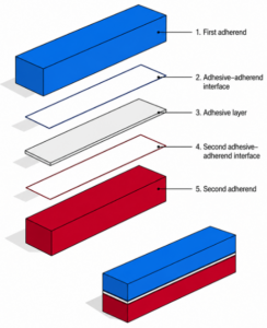
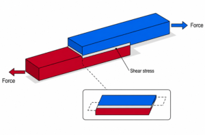
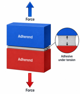
Another consideration is the loading mode. The loading mode describes how an external force or stress is applied to the component or joint and includes primary types such as shear, tension, compression, peel, and cleavage, as well as combinations of these. Shear stress acts parallel to the bond line and attempts to slide the adherends past each other. Tension acts perpendicularly to the bond line and attempts to pull the adherends directly apart. Compression attempts to push the adherends towards each other. Peel and cleavage concentrate stress near the adherend edge.
Most adhesive joints perform better when force is evenly distributed across a large surface area. They also perform better under shear or compressive stress than under peel or cleavage. Peel and cleavage can trigger separation at the edge, causing it to propagate across the bond. However, stress is rarely distributed perfectly evenly throughout an adhesive joint. Instead, the ends or edges may still carry more stress than the central region. Factors that determine where stress concentrates include the stiffness of the adherends, the thickness of the adhesive, the geometry of the joint, and the direction of loading.
Why Joint Geometry Matters
Joint geometry determines the bonding area, the configuration of the components, the direction of the load path, and the types of stress applied to the adhesive.
Two joints with the same adhesive and materials can have significantly different strengths because their joint geometries are different. The purpose of an effective joint is to transfer forces into and out of the bonded area without creating significant stress concentrations. A well-designed adhesive joint typically:
- Provides sufficient bonding area
- Transfers force evenly between adherends
- Has a shear or compression stress type
- Minimizes peel and cleavage stress
- Reduces behind and unusual loading
- Avoids abrupt changes in thickness or stiffness
- Maintains suitable bond-line thickness
- Limits serious stress concentrations
- Allows complete adhesive application
- Allows proper assembly and curing.
This guide provides information about the types of joints and provides an overview of when each joint is suitable to use. However, you must use your discretion to assess your unique situation and take into account the considerations that apply to it.
How Adhesive Joints Are Classified
Adhesive joints can be classified according to their geometry, the arrangement of adherends, or the loads they are intended to carry.
Classification by Component Arrangement
The configuration and arrangement of each adherend provide a means of classifying an adhesive joint.
Overlapping Joints
In an overlapping joint, one adherend extends over another. The adhesive is placed between the overlapping surfaces. Lap joints are a primary example because their large bonded area allows them to carry substantial loads through shear stress.
End-to-End Joints
End-to-end joints occur when the ends of the two adherends fit together. A basic butt joint is the simplest example. Other types of end-to-end joints include modified versions such as scarf, beveled, and stepped joints.
Perpendicular Joints
In a perpendicular joint, one adherend meets another at or near a right angle. T-joints and corner joints are common examples. These joints are common in boxes, frames, cabinets, panels, structural assemblies, and stiffened components. The type of stress these joints impose on the adhesive determines their performance.
Concentric Joints
A concentric joint is when one cylindrical adherend fits inside or around another. The adhesive bond line is the area between where the interfaces of the two cylindrical substrates come together.
Surface Mounted Joints
In a surface-mounted joint, the component is bonded to the face of a larger panel. Such joints are common in sheet-metal assemblies, building panels, composite structures, and product enclosures.
Classification by Joint Geometry
Classification by Loading Mode
Classifying joints by loading direction refers to the five principal loading modes in adhesive joints.
Shear
Tension
Compression
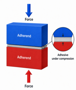
Compression stress occurs when the forces push the adherends toward each other. Adhesives generally tolerate compression stress well, but excessive compression may deform the adherends, squeeze uncured adhesive out of the joint, or damage a brittle adhesive layer.
Peel
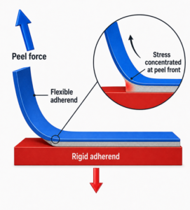
Peel stress occurs when the forces pull the adherends away from the adhesive layer at an angle. The load becomes concentrated along a narrow line at the edge of separation. Adhesive joints generally do not respond well to peel stress because the load is not distributed evenly.
Cleavage
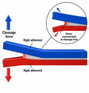
Cleavage stress occurs when the forces pry two rigid adherends apart from one edge of the joint. Peel stress is similar to cleavage stress because they produce a strong concentration of force near the edge of the bond. Peel usually involves at least one flexible adherend, while cleavage incorporates two rigid adherends.
Objective of Adhesive-Joint Geometry
The main objective of adhesive joint design is to distribute force over the largest practical surface area while minimizing peel or cleavage.
A well-designed joint ideally should:
- Place most of the stress under compression or shear.
- Have a sufficient bonded surface area.
- Avoid sharp changes in geometry.
- Reduce stress concentration at the edges of the bond.
- Maintain a suitable and consistent bond-line thickness.
- Protect the bond from harmful environmental exposure.
- Account for differences in material stiffness and thermal expansion
- Be practical to configure, clamp, inspect, and repair.
The following sections examine each major adhesive-joint geometry and its corresponding variations along with their advantages, limitations, and stresses.
Butt Joints
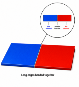
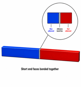
A butt joint forms when the edge of one adherend is placed directly against the end of another—the adhesive forms a bond line where the two opposing surfaces meet. The two primary categories of butt joints are end-to-end butt joints and edge-to-edge butt joints.
Plain Butt Joint
A plain butt joint is one of the simplest adhesive joint designs. A plain butt joint forms where two flat surfaces meet without an overlap, bevel, step, or reinforcing member. If forces pull the adherends apart, the adhesive is placed under tensile stress. If the forces pull the adherends in a sliding motion, the adhesive may experience shear stress. If careful preparation is not followed during adhesive application, resulting in uneven distribution, the joint may develop cleavage stress.
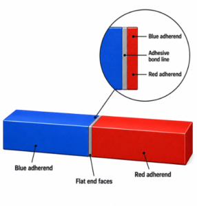
Advantages: Plain butt joints are simple to prepare and require very little machining if any. The amount of adhesive required is also low. The resulting product produces a flat external surface. The plain butt joint is useful when overlap is not possible.
Edge-to-Edge Butt Joints
End-to-End Butt Joint
Reinforced Butt Joint
Lap Joints
Single-Lap Joint
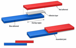
The primary concern with single lap joints is that the force does not pass through the same plane because one force acts through the center of one adherend while the other acts through the center of the other adherend. This creates an eccentric load, which may cause the adherends to rotate or bend slightly under pressure. This deformation introduces peel and cleavage stress near the ends of the overlap. This is why single lap joints are suitable when the adherends are thin and flexible, some bending can be tolerated, the expected loads are moderate, or manufacturing costs must remain low.
Double Lap Joint
A double lap joint position on an adherend between the two outer adherends and adhesives applies to both sides of the central adherend, resulting in a double bond line.
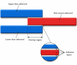
A double lap joint is useful because it provides twice the bonded area of a single lap joint, can carry a greater load, distributes the load across two adhesive layers, and reduces bending when the joint is symmetrical. Additionally, it produces less peel stress than a single lap joint and aligns applied forces better. Ideally, the configuration should be symmetric because it balances the load better on both sides.
The limitations of the double lap joint are that it requires a second adherend, uses more adhesive, is heavier than a single lap joint, is difficult to inspect, requires more work, and the bond can become unbalanced if the two bond lines vary too much.
Joggled Lap Joint
A joggled lap joint is a modified lap joint in which one or both adherends contain an offset or joggle near the overlap. The joggle allows the overlapping sections to fit together while keeping the main areas of the adherends aligned. With a standard lap joint, one adherend is positioned above another, which can cause bending due to an offset load path and create peel stress near the ends of the bond. A joggled configuration reduces this offset by forming a step between the two adherends. This configuration reduces the peel stress, producing a smoother or nearly flush external surface.
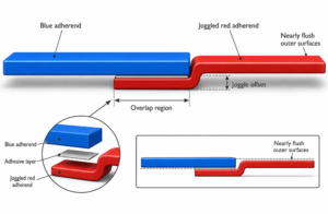
A joggled lap joint does not entirely exempt the assembly from elevated peel stress, which can still concentrate near the corners of the overlap. Joggled lap joints are common with sheet metals, thermoplastics, laminates, and composite materials. The integrity of a joggled lap joint depends on whether the adherends can be formed, molded, machined, or laid up without introducing cracks, wrinkles, and residual stress.
Recessed Lap Joint
A recessed lap joint is a modified lap joint in which the material is removed, displaced, or molded from one or both adherends to create an overlapping recessed area. The ends of the adherends fit into the recessed area, allowing the components to overlap in a flush external surface.
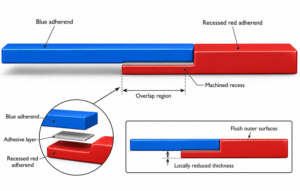
The recesses at the ends of the adherends allow the load to transfer through shear, minimizing peel stress. Recesses are generally produced by machining or routing, molding, or press forming. Avoid abrupt internal corners, which can concentrate stress and weaken the adherend. Rounded corners and gradual tapers are a preferable way to transition between full-thickness and recessed sections.
Recessed lap joints are used in woodworking, machine components, plastics, sheet materials, laminates, and composite structures.
A recessed lap joint differs from a joggled lap joint because a recessed joint uses a locally reduced area to receive the overlap, whereas the joggled joint uses a bend to offset the adherend.
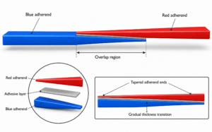
Tapered Lap Joint
Scarf and Stepped Joints
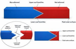
A scarf joint is formed by cutting or shaping the ends of two adherends at matching angles and bonding the inclined surfaces together. The joint uses a curved diagonal bonding surface, and the ratio between the inclined surface and the adherend thickness is called the scarf ratio. For instance, a joint with an inclined length ten times the adherend thickness has a scarf ratio of 10:1. A greater scarf ratio has a longer bonded surface and a shallower angle.
Scarf joints transfer load through shear because the force acts parallel to the inclined bond line. Shallow scarf angles work well because they increase the bonding area, allow for more seamless transfer of force through shear, and help maintain alignment of the connected components. Stress is not entirely uniform, as the ends of the joint can still experience higher stresses. Scarf joints require machining or cutting, and you must pay careful attention to ensure proper alignment.
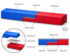
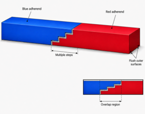
A stepped joint is formed through the cutting or formation of a sequence of matching steps into the ends of two adherends. The stepped surfaces fit together and bond across several horizontal and vertical sections. A stepped joint may be considered a modified butt or scarf joint. The load transfers more evenly through several smaller bonding connections.
Plain Scarf Joint
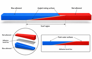
A regular scarf joint consists of continuous inclined surfaces on each adherend that fit neatly. The simple-scarf-joint design is commonly used in wood members, composite repairs, laminated structures, sheet materials, and long strips.
Double Scarf Joint
Single Stepped Joint
Multiple Stepped Joint
Strap Joints
Single-Strap Joint
Double Strap Joint
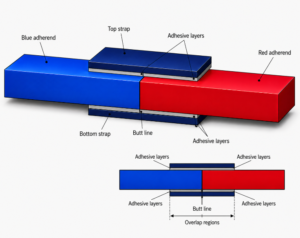
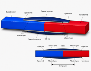
Tapered Strap Joint
T-Joints
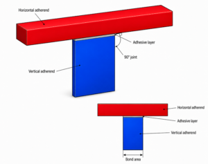
Plain T-Joint
Filleted T-Joint
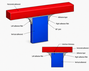
A filleted T-joint is a modified T-joint in which additional adhesive is applied along the lines where the adherends touch. The adhesives along the bond line on both sides form a curved or triangular transition called a fillet.
A filleted T-joint allows for more gradual load transfer and can increase the bonding area. It may also reduce stress concentrations at the joint edge and better support the perpendicular adherend. Peel and cleavage stress are also reduced as the edge of the bond line is now sealed.
Flanged T-Joint
Instead of the vertical adherend forming a T-joint with the horizontal adherend, the single flanged T-joint is supported by an additional flange and helps create a larger bonding surface. A single flanged T-joint has a flange that extends to one side and may have a molded base or a curved foot.
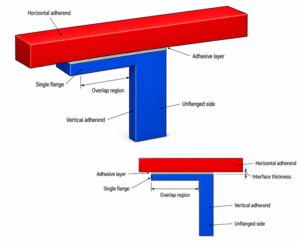
A flanged T-joint provides greater bonding area and transfers load through shear across the flange. It adds stability to the vertical adherend and reduces dependence on the narrow web edge.
A flanged joint can still create peel stress at the outer edges and may require molding, forming, or attaching an additional component. Additional modifications such as tapering may help the flange transition stiffness more gradually and reduce stress concentration.
Likewise, a double-flanged T-joint may have a flange on both sides.
Reinforced T-Joint
A reinforced T-joint uses additional securements to support the connection. Reinforcements may include angle brackets, triangular blocks, gussets, tapes, cleats, laminated plies, composite overwraps, and mechanical fasteners.
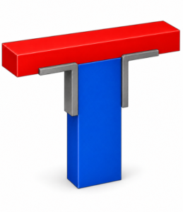
Reinforcement distributes the force more gradually and provides additional support for the web edges. It is advisable to avoid abrupt changes in stiffness to avoid moving the stress concentration from the original joint to the end of the reinforcement.
Corner Joints
Corner joints connect two adherends at or near their ends to form a corner. The angle is typically 90 degrees, although other angles may be appropriate. Corner joints are commonly used in boxes, cabinets, frames, containers, ducts, housings, furniture, panels, and structural enclosures.
Butt Corner Joint
A butt corner joint is formed when the butt or end of one adherend is bonded to the face of another adherend at a right angle. Butt joints are generally easy to prepare and require little machining. They are easy to assemble and understand, and they suit boxes or enclosures.
Mitered Corner Joint
A mitered joint has two beveled ends of the adherends, and they meet at an angled bond line. Each adherend is generally cut at a 45-degree angle to form a 90-degree corner.A mitered joint is good for a clean external appearance and for hiding the end surfaces of the adherends.

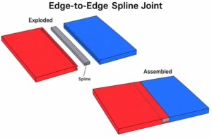
It does require cutting and preparation. It is sensitive to angular errors, so precision is required when preparing the joint. It may require reinforcement to counteract cleavage along the inside or outside of the corner. It may also slide during clamping. Reinforcements that work well with mitered corner joints include splines, keys, biscuits, dowels, or fillets.
Flanged Corner Joint
A flanged corner joint uses an internal flange to create a larger bonding surface at the corner. The flange is formed or machined at roughly 90 degrees and bonded to the face of the mating adherend. The geometry transfers most of its load through shear instead of concentrating it at a narrow edge.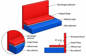
Flanged corner joints are common in sheet metal assemblies, composite shells, molded plastic parts, cabinets, and enclosures. The flange must be wide enough to support the bond area, but bending the corner can still produce peel stress at the flange edges.
Gusseted Corner Joint
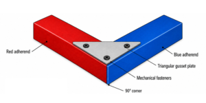
A gusseted corner joint uses a separate plate, block, or angled piece called a gusset to reinforce the adhesive joint between two adherends. The gusset is attached to the faces of both adherends and provides a more direct path for loads to transfer across the corner. Gussets can be installed on the inside, outside, or on both sides of the joint. Gussets may be made from wood, metal, plastic, or composite material.
A gusset prevents bending, cracking, and impact by improving stiffness. Nevertheless, stress concentrations can occur where gussets meet at abrupt angles, so rounded or tapered ends are preferable where fatigue is expected.
Cylindrical Adhesive Joints
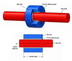
Cylindrical adhesive joints use overlapping round parts to connect two adherends. Common examples include shafts bonded into hubs, tubes inserted into sockets, and sleeves fitted over adjoining members. The circular overlap provides a large bonding area and transfers force through shear while torque is transferred around the circumference. Avoid tight fits, which can scrape adhesive away during assembly.
Socket and Spigot Joint
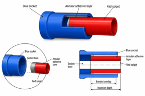
A socket and spigot joint consists of a projecting cylindrical end called the spigot inserted into a matching socket. Adhesive is applied to the annular space between the outside of the spigot and inside of the socket. This provides a large bonding area and transfers load primarily through shear, while the circular interface can transmit torque. There should be enough clearance to allow a path for displaced air or hydraulic pressure.
Shaft-To-Hub Joint
Tube-in Socket Joint
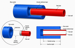
A tube-in socket joint is formed by inserting a hollow tube into a deep cylindrical socket. The socket’s inner wall bonds to the tube’s outer surface. This geometry is commonly used in handles, frames, pipes, sporting equipment, and composite components. It effectively transmits axial and torsional loads when the bond is concentric and uniform. Avoid sharp ends that concentrate stress at the bond termination, and consider a tapered socket or internal stop.
Sleeve Joint
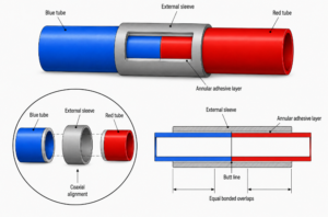
A sleeve joint forms when two cylindrical components are bonded together using a separate cylindrical sleeve to reinforce the connection. The sleeve helps maintain alignment and carry axial, bending, and torsional loads across the joint line. You can modify the ends by tapering to reduce abrupt stiffness changes and edge stresses. A sleeve is usually made from the same material as the adherends or from a mechanically and chemically compatible material.
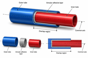
Coaxial Tube Joint
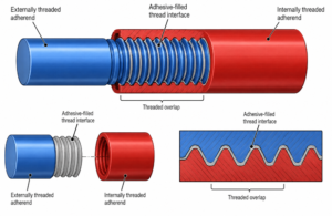
Bonded Threaded Joint
Mortise and Tenon Joints
Traditional Mortise and Tenon Joint
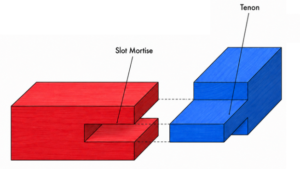
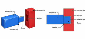 A traditional mortise and tenon joint has a rectangular tenon cut on the end of one adherend, and a matching mortise cut into the other. The tenon cheeks provide the primary bond line, while the shoulders support the mortised member and keep it square. Apply the adhesive to both the mortise and tenon surfaces before assembly. The joint resists shear, bending, and racking because the load transfers through the interlocking wood geometry and the adhesive. Proper installation requires careful attention to thickness, shoulder width, grain direction, moisture content, and fit.
Blind Mortise and Tenon Joint
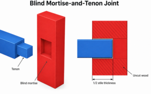
A blind or stopped mortise and tenon joint uses a mortise that does not pass completely through the mortise. The opposite end of the face is left clean and without interruption. These joints are commonly used in furniture, doors, and cabinet frames. The bottom of the mortise must allow enough space to avoid hydraulic pressure and to allow for excess adhesive. The strength of a mortise joint depends on the surrounding wood and the bonded tenon cheeks.
Through Mortise and Tenon Joint
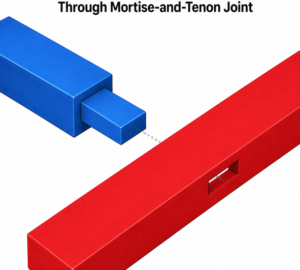
A through mortise and tenon joint has a mortise that passes entirely through the receiving adherend. The tenons extend into and through the opposite face of the adherend and are visible after assembly. The exposed end can be trimmed flush, wedged, pinned, or left as a decoration. The mortise remains open and can cause adhesive and air to escape during assembly which improves seating. The joint provides the option to inspect it from both sides. Sufficient wood is needed around the mortise to prevent splitting.
Haunched Mortise and Tenon Joint
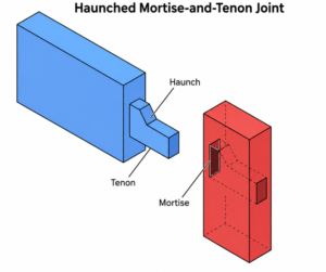
A haunched mortise and tenon joint includes a shortened companion called a haunch alongside the main tenon. The haunch fits into a shallow recess or groove near the edge of the mortise. It keeps the members aligned, resists twisting, and prevents a rail or frame member from cupping at the edge. Haunched tenons are common in applications that involve a panel groove. Most of the load is carried by the main tenon while the haunch supports the outer edges. The geometry is definitely more challenging to machine but the extra support may be worth it.
Wedged Mortise and Tenon Joint
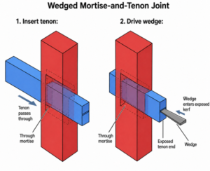 A wedged mortise and tenon joint utilizes one or more wedges to expand or lock the tenon after insertion. Typically, in a wedged through mortise and joint there are slots made in the tenon from which wedges are driven into from the opposite side. The wedges spread the tenon against the mortise walls providing mechanical resistance to withdrawal. The wedging action needs careful attention because excessive expansion can split the receiving member. Additional attention is required to the grain direction, wedge taper, slot length, and remaining wood around the mortise.
Pinned Mortise and Tenon Joint
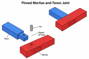
A pinned mortise-and-tenon joint has a tenon inserted into the mortise with a slot cut out for a pin or dowel. The pin prevents the tenon from withdrawal and can keep the joint strong in the event the adhesive weakens. It can also provide extra support during curing. In a draw-bored version, the hole in the tenon is marginally offset so the pin can keep the shoulder tightly against the receiving member during insertion. The offset should be small enough to avoid splitting the tenon.
Loose Tenon Joint
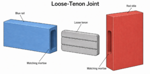
A loose tenon joint uses a strip or block as a tenon instead of cutting the tenon out of one of the adherends. Mortises are cut into both adherends, and the adhesive is applied and the tenon is inserted into both cavities. Loose-tenon joints prove especially useful when the adherends are thin, curved, or difficult to machine. Special attention should be put toward the mortise and tenon fit to ensure proper alignment and to avoid positional errors.
Dowel and Biscuit Joints
Dowel and biscuit joints use wooden inserts to align and connect adjoining adherends. Dowels fit into round holes while biscuits use shallow crescent shaped slots. Adhesives are applied to the inserts and slots, and the load is then transferred through the insert and surrounding wood. These joints are common in cabinetry, furniture, and panel construction because they allow assembly without mechanical fasteners. Careful attention is required for preparation of dowels and slots to ensure proper fit.
Dowel Joint
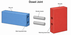
A dowel joint uses one or more cylindrical pins to fit into matching holes on both members. Adhesive is applied to the dowels and the hole walls before they are pressed and locked into place. The dowels provide alignment and bonding area where the load is then transferred through shear while preventing withdrawal across the joint. Grooved or fluted dowel modifications allow trapped air and excess adhesive to escape during insertion. Careful attention is required to ensure proper dowel fit as excessive tightness can cause the adhesive to be removed or for the wood to split. On the contrary, loose dowels may not provide sufficient alignment.
Edge-to-Edge Dowel Joint
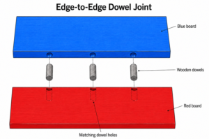
An edge-to-edge dowel joint is when the edges of two adherends are connected using dowel pins across the joint line. Matching holes are drilled into the edges of both adherends, and the dowels are inserted with adhesive applied. The dowels add local reinforcement and reduce movement during clamping. They are used in applications such as panels, tabletops, shelves, and other wood assemblies.
End to Face Dowel Joint
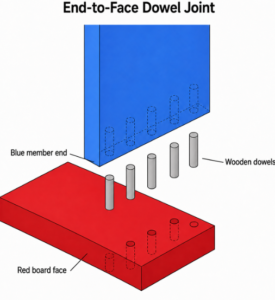
An end-to-face dowel joint connects the end of one adherend to the face of another adherend. The dowels are inserted into holes that are drilled on both adherends. This geometry is common in cabinet carcasses, shelving, frames, and furniture. The dowels provide far better anchorage than just a traditional butt joint would with adhesive applied to the edges. The dowels also support load transfer, but they must be kept shallow enough, so they don’t weaken or break the opposite surface.
Edge-to-Edge Biscuit Joint
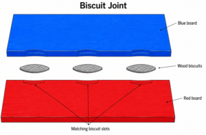
A biscuit joint uses a thin, oval shaped wafer to fit into matching crescent shaped slots. The wafer formally regarded as a biscuit is positioned into the slot walls after adhesive application to join the adjoining adherends. Biscuits are mainly constructed from compressed wood, and a water-based wood glue can cause them to swell and tighten the fit. Biscuit joints are useful in panels, frames, cabinets, and mitered assemblies.
T-Biscuit Joint
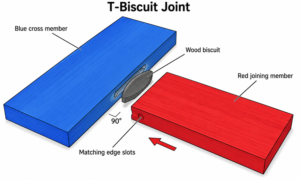
A T-biscuit joint connects the end of one adherend to the face of another adherend at a 90-degree angle with slots for the biscuits in both adherends. A slot is cut into the end of one adherend, and another slot is cut into the face of the other adherend. This arrangement is common in fixed shelves, partitions, and cabinet dividers. The adherends must be thick enough to support the slots without breaking through.
Mitered Biscuit Joint
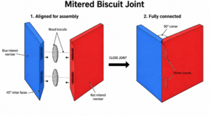
A mitered biscuit joint uses two miter-cut members with slots and inserts a biscuit into them at an angled interface. The biscuits improve miter alignment during clamping and add reinforcement that would otherwise depend on a narrow end-grain bond. Mitered biscuit joints are common in frames, boxes, trim, and mitered corner configurations. Slots must be cut carefully to ensure the right fit and the biscuit size needs to be kept thinner for thin members. Provide support during curing because mitered corners can be exposed to opening and peeling forces.
Interlocking Wood Joints
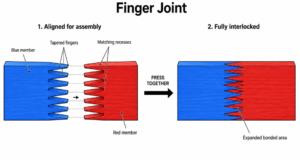
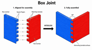
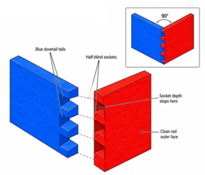
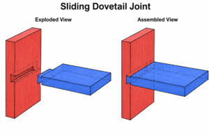
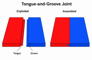
Interlocking wood joints use shaped projections, recesses, tongues, fingers, or grooves that fit together before applying the adhesive. The geometry provides improved alignment and mechanical resistance to stress. These joints distribute loads over larger areas and reduce dependence on end-grain adhesion. Interlocking wood joints are commonly used in furniture, cabinetry, boxes, flooring panels, and structural timber products. Machining skills are required for manufacturing interlocking wood joints.
Finger Joint
Box Joint
Dovetail Joint
Sliding Dovetail Joint
Bridle Joint
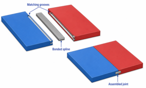
Spline Joint
Tongue and Groove
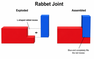
Rabbet Joint
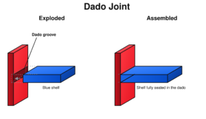
Dado Joint
How to Choose an Adhesive-Joint Type
Determine the Expected Loads
Identify the Adherend Materials
Evaluate the Available Bonding Area
Consider Manufacturing and Assembly
Consider the Operating Environment
Environmental conditions during manufacturing, assembly, and curing phases such as temperature, moisture, chemical, sunlight, corrosion, and outdoor exposure can all impact the performance of a bonded joint. The adhesive and adherend should remain compatible with each other throughout the lifecycle of the joint and expected service conditions. Warm temperatures can soften some adhesives and increase the rate of degradation, while cold temperatures can make some adhesives brittle. Water and humidity can degrade the adhesive interface, swell wood, or promote corrosion beneath a bonded metal joint.
Environmental changes can also affect how dissimilar materials expand and contract and whether they develop significant internal stress. Additional modifications such as flexible adhesives, shorter bonded sections, tapered transitions, or adjusted geometries may be required to accommodate movement.
Determine Inspection and Repair Requirements
Inspection after assembly is easier for some joints in comparison to others. Lap joints and external patches provide visible bond edges, but mortises, sleeves, sandwich panels, and sockets can hide internal defects. Visual inspection can reveal gaps, adhesive squeeze-out, misalignment, and edge lifting, but it cannot visibly confirm the condition of the hidden interface. If available, you may have to resort to imaging technology such as ultrasonic, radiographic, or thermographic testing for important structures.
Repair and disassembly should also be taken into account to determine if a joint can be accessed, heated, cut apart, cleaned, and rebonded without damaging the surrounding components.
Minimize Peel and Cleavage
Adhesives do not respond well to peel and cleavage stress, which is why joint design should aim to minimize them. Adhesive joints should be shaped so the bond carries load through shear or compression. Peel concentrates force along a moving edge, while cleavage opens the joint from one side and emphasizes stress near the end of a bond. These peel and cleavage conditions can cause bond failure even when the bonding surface is large. Bond edges should be protected from direct lifting, impact, and moisture entrance. Added reinforcements may be required if peel cannot be eliminated.
Select and Test the Final Geometry
After satisfying the primary requirements, compare a list of the top suitable joint geometries before settling on a workable option. Contemplate their load paths, bonding areas, material compatibility, manufacturing difficulties, environmental durability, access, repairability, weight, and cost economics.
You should then create a smaller version of the joint using a mini model of representative adherends, surface preparation, adhesive thickness, curing conditions, and assembly tolerances. Tests should imitate the expected loading direction and operating environment as close as possible to the actual predicament. Take into consideration aging, moisture exposure, thermal cycling, fatigue, impact, and sustained loading. Always follow the correct engineering standards, adhesive-manufacturer guidance, and authorized design procedures when working with adhesive joints.
Conclusion
This publication provides a comprehensive list of common types of adhesive joints, but it is not an exhaustive list. If there is a specific type of joint you would like to see added, please leave your suggestions in the comments below. If there are any errors or omissions, kindly bring them to our attention.
