

One of the main purposes of an adhesive joint is to transfer force from one adherend to another adherend through a relatively thin layer of adhesive. How successfully an adhesive joint manages its stress load depends not only on the strength of the adhesive but also on how the joint converts the external load into stress within the adhesive, at the interfaces, and around the joint itself.
Five main loading modes are common in adhesive bonding: shear, tension, compression, peel, and cleavage. These modes all impact the bond in different ways. Adhesive joints perform best when the load is transferred through shear, tension, or compression. Peel and cleavage joints do not hold up well with adhesives because they concentrate stress near the edges.
Joints that are intended to carry stress through shear and tension may resort to developing peel and cleavage stress if the joint is not properly configured. For example, a butt joint positioned in tension may develop cleavage if the force is slightly misaligned. Likewise, a single-lap joint positioned in shear may develop peel from adherend bending. Knowing that these types of interactions can impact bond integrity is important to design the joint around actual stress distribution rather than relying on nominal adhesive strength.
What is Stress in an Adhesive Joint?
Stress can be described as an internal force acting over a defined area of a material. In its simplest equation:
Stress = Force ÷ Area
Stress can be quantified in pascals, megapascals, pounds per square inch, or similar units. The correct equation is identified based on the direction of the force. A force that acts perpendicular to the bond produces normal stress while a force that acts parallel to the bond produces shear stress.
Stress is not the same as load. A load is the external force or movement applied to an assembly. Stress is the internal response as the joint assembly transfers that load. Stress is internally produced in the adhesive, adherends, and the interfaces of the assembly. The same external load can create varying stress distributions conditional on the geometry, bonding area, material stiffness, and alignment of the joint.
For instance, a centered tensile load that is placed upon a broad, symmetrical joint can produce a relatively uniform normal stress. If the same load is positioned away from the center line, the load can bend the adherends and concentrate tensile stress along the edge. The magnitude of the stress has not changed but the positioning changes how the joint handles it.
Several components of an adhesive joint influence this stress response:
- The adhesive is the bonding substance that transfers force between the two adherends
- The adherends are the components being joined
- The bond line is where the adhesive sits between the two adherends
- The interfaces are the boundaries where the adhesive contacts each adherend.
Bond failure can occur at any of these locations so that tells us that stress is not confined to the adhesive layer.
Dividing the force by the area provides us with average stress but it does not show what happens in concentration at specific locations. Dividing the applied force by the area suggests an equally distributed stress profile but in practical terms stress can concentrate at certain points. Factors such as adherend deformation, joint eccentricity, abrupt edges, voids, thickness variation, and material differences can create non-uniform stress fields. A bond with a lower overall stress value can still failure if higher local stress develops near an overlap end, corner, crack, or defect. Therefore, it is important to pay attention to the nominal stress and local peak stress.
The Five Primary Loading Modes in Adhesive Joints
The five primary loading modes have been classified according to the direction and distribution of the forces acting on the joint:
- Shear force acts parallel to the bond and attempts to slide the adherends past each other.
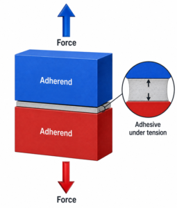
- Tension acts perpendicular to the bond and pulls the adherends directly apart.
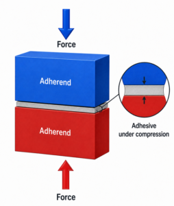
- Compression acts perpendicular to the bond and pushes the adherends together.
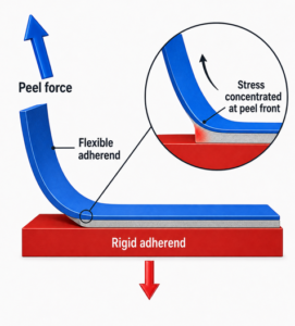
- Peel slowly lifts at least one flexible adherend away from another.
- Cleavage pries two rigid adherends apart from one end.
While these are useful theoretical models, it does not mean that every joint is loaded using only one specific loading mode. Local concentrations of stress may vary, and a single joint can combine multiple loading modes. For example, single lap joints combine shear with peel because their load paths are offset. The dominant loading mode should guide joint design, but the secondary stresses should not be ignored. This is especially important when you are considering the lifecycle of the joint.
Shear Stress
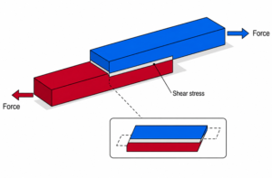
Shear stress occurs when two parallel adherends attempt to slide past each other. A typical example of a joint that produces shear stress is a lap joint.
How Shear Stress Acts
Shear stress acts parallel to the plane of the adhesive layer. It attempts to slide one adherend past another while the adhesive resists the sliding movement.
A single lap joint can experience shear stress when the adherends are pushed past each other in opposite directions.
The nominal average shear stress can be calculated by dividing the force by the bonded area:
Average Shear Stress = Parallel Force ÷ Bonding Area
This calculation is a start to estimate the type and amount of stress the joint could experience. It does not mean that shear stress is equal at every point. As the adherends stretch, bend, and transfer load into the adhesive, new stress concentrations can develop at varying magnitudes.
Adhesive Joints Commonly Loaded in Shear
In this section, we list a number of common joint types that are loaded in shear.
Common examples include:
- Single lap joint
- Double-lap joints
- Step joints
- Scarf joints
- Sleeve joints
- Strap joints
- Shaft-to-hub joints
- Socket-and-spigot joints
- Coaxial tube joints
- Skin-to-stiffener joints
- External patch joints
- Face-to-face laminations
Shear-Stress Distribution
The shear stress in a bonded overlap is usually not evenly distributed. In a typical lap joint, stress concentrates near the ends of the overlap because this is where the force enters and leaves the adhesive layer. The center may be more stable and carry a smaller portion of the total force.
The non-uniformity is partially caused by the difference in lengthwise pulling force carried by each adherend. At the beginning of the overlap, the first adherend carries most of the lengthwise load. As the adhesive gradually transfers the load into the second adherend, the force carried by the first adherend decreases while the force carried by the second adherend increases. As a result, the force concentrates near the ends of the overlap, and the center bears less stress.
Joint eccentricity can further increase the local stress. Joint eccentricity means that the stress does not travel along straight lines. This offset makes the joint bend or rotate while being pulled, creating additional peel stress at its edges.
In a single lap joint, increasing the overlap length can reduce the average sheer stress, but it does not reduce the stress at the edges in direct proportion.
Advantages and Limitations of Shear Loading
Shear is compatible with adhesives because it allows force to be transferred across a large bonding area, and adhesives generally favor continuous load distribution. Correctly configured lap, scarf, and cylindrical joints can support substantial loads without the need to drill holes through the adherends.
However, shear does have its limitations:
- Stress concentrates near overlap ends and edges
- Peel stress can be caused by eccentric loading
- Creep can develop under a sustained load
- Adherend may bend or rotate
- Fatigue can occur under repeated loading
- Reduced performance at hot temperatures
The optimal shear-loaded designs align the force path, use appropriate overlap proportions, and provide gradual or tapered load transfer. Double-lap, scarf, stepped, or tapered geometries are effective at reducing joint eccentricity and softer stress transition.
Tensile Stress
How Tensile Stress Acts
Adhesive Joints Commonly Loaded in Tension
- Face-to-face joints pulled directly apart
- Butt joint where the load is distributed along a common center line or axis
- Stud-to-panel joints
- Insert joint
- Skin-to-core joints under through-thickness loading
- Sandwich-panel skins subject to local uplift
Tensile-Stress Distribution
- The load is perpendicular to the bond.
- The force passes through a common axis
- The adherends have near-identical stiffness
- The bonding surfaces are flat and parallel.
- The adhesive layer has a consistent viscosity and thickness.
- The joint is free from voids and edge defects.
Advantages and Limitations of Tensile Loading
- Sensitivity to load misalignment
- Bending caused by uneven configurations or adherends
- Lifting of edge in flexible materials
- Local stress developing around defects
- Through-thickness weakness in composite or sandwich cores
- Difficulty maintaining uniformity of load distribution.
Compressive Stress
How Compressive Stress Acts
Adhesive Joints Commonly Loaded in Compression
- Face-to-face joints beneath clamping or bearing loads
- Laminated members carrying compressive stress
- Bonded blocks or pads
- Sandwich panels under localized pressure
- Bonded joints in columns or supports
- Sealed flange joint
- Mortise and tenon under bearing
- Adhesive layers underneath machine bases or inserts
- Joint regions compressed by mechanical fasteners
Compression, Buckling, and Adhesive Squeeze-Out
Advantages and Limitations of Compression Loading
- Core or surface crushing
- Adhesive buckling
- Local indentation
- Plastic deformation
- Long-term creep
- Adhesive leakage from unconfined surface area
- Uneven bearing pressure
Peel Stress
How Peel Stress Acts
Why Peel Stress Is Damaging
Adhesive Joints Susceptible to Peel
- Adhesive tapes
- Flexible sheet seams
- Single-sided patch joints
- Labels and films
- Thin metal or plastic lap joints
- Flexible laminates
- Membranes and fabrics
- Skin-to-core bonds
- Bonded trim
- Joints with lifted or unsupported edges.
Methods for Reducing Peel Stress
Apply loads in the plane of the bond.
- Increase adherend stiffness near the joint.
- Avoid pulling directly on a flexible edge.
- Use a double-lap or double-sided configuration.
- Taper patch, strap, or doubler edges.
- Add an adhesive fillet at the overlap end.
- Use rounded terminations rather than sharp ones.
- Extend or fold a flexible adherend to allow gradual transition of force.
- Protect exposed edges from impact and lifting.
- Use mechanical fastening where unavoidable peel loads are significant.
- Select an adhesive with better toughness and peel resistance.
- Ensure adequate wetting and correct surface preparation.
Cleavage Stress
Cleavage stress develops where one rigid adherend is pried away from another.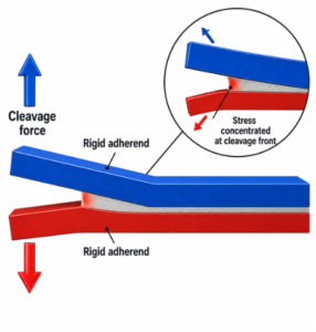
How Cleavage Stress Acts
Cleavage occurs when two rigid adherends are pried apart from one end of the joint. This force creates a strong tensile-stress concentration near the opening edge.
This action resembles opening a rigid lid or separating two interlocked plates with a wedge. The adherends do not separate in a continuous flexible strip like with peel, but the joint still opens progressively from one side.
Cleavage converts an otherwise broad bonded area into an edge-dominated load path. Therefore, a small angular misalignment can prove more damaging than a properly centered tension load.
Adhesive Joints Susceptible to Cleavage
Peel and cleavage follow similar mechanisms, but peel occurs with flexible adherends while cleavage occurs with rigid adherends.
Cleavage can occur in:
- Butt joints with off-center loads.
- Corner joints.
- Rigid lap joints prone to prying.
- Flange joints.
- Bonded brackets.
- Stiff external patches.
- T-joints under overturning loads.
- Rigid covers or panels lifted from one side.
- Joints susceptible to bending movements.
- Assemblies contain gaps or uneven supports.
Methods for Reducing Cleavage Stress
Cleavage opens a relatively rigid joint from one end, producing a strong stress concentration near the opening edge. There are several methods you can use to reduce cleavage by improving load alignment and making the transfer of force more gradual:
- Align the applied force with the center of the bonded area
- Avoid unsupported prying loads
- Use balanced or symmetrical joint arrangements
- Add gussets, flanges, straps, or doublers where possible.
- Taper stiff reinforcements
- Use scarfed or stepped transitions
- Increase the joint radius at corners
- Add adhesive fillets where permitted
- Reduce gaps and angular misalignment.
- Select an adhesive with cleavage resistance.
- Use mechanical fasteners where appropriate
The objective is to redirect force from concentrated areas to a more even distribution of the load.
Frequently Asked Questions
This section covers frequently asked question related to stress in adhesive joints.
What is the best type of stress for an adhesive joint?
Shear and compression are usually the best types of loading modes for adhesive bonding. Shear provides a large bonding area to transfer force, while compression pushes the adherends toward the adhesive. Uniform tensile stress may also be favorable if the force is centered and distributed across a complete bond. The best loading mode will also depend further on the adhesive, adherends, geometry, environment, and duration of loading.
What is the worst type of stress for an adhesive joint?
Peel and cleavage are generally the worst types of stress for an adhesive joint because they concentrate stress along an edge. Once the separation begins, the effective bonding area becomes smaller, and failure starts to occur. The severity of peel or cleavage stress depends on the adherend flexibility, joint stiffness, adhesive toughness, loading angle, and edge condition.
Is shear stronger than tension in an adhesive joint?
Not necessarily, because shear strength and tensile strength cannot be compared without the appropriate test methods or geometric considerations. Joint designers typically prefer shear because the load is easier to distribute over a large area. Alignment is the key factor that determines the feasibility of a shear or tensile loading mode because misaligned adherends can begin to develop peel or cleavage stress.
What is the difference between peel and cleavage?
The difference between peel and cleavage stress is mainly that peel involves flexible adherends, while cleavage involves rigid adherends. Either way, both begin separating at the edge.
Can an adhesive joint experience several stresses at once?
Yes, adhesive joints may experience multiple stresses at one time, usually from different angles. A single lap-joint can carry shear and peel while a bonded bracket may experience shear, tension, and cleavage. The dominant loading mode is useful for describing the adhesive joint, while the secondary stresses indicate where failure may begin to occur.
Does increasing the bonding area always increase strength?
Not necessarily, because increasing the bonding area may result in lower average stress, but concentrations can still develop at failure points, resulting in reduced strength for the overall joint. Whether increasing the bonding area will effectively increase strength depends on the geometry, stiffness, load alignment, and adhesive properties.

1 Comment
Pingback: Factors That Affect Adhesive Joint Strength - Bonding Station